Power Factor Connection Diagram Inside The Capacitor Bank Pa
What are the components of a substation Rlc parallel circuit (power factor, active and reactive power Explain in detail about power factor?
Wiring Diagram of Power factor correction relay - YouTube
Complete auto power factor panel wiring diagram Power factor Reply delete
Difference between unity, lagging, leading power factor, definition
Power factor and power factor correction, pt 2How to wire power factor correction panel Connection power factor correction capacitor wiring diagramPower factor controller wiring diagram.
Power factor wiring diagramPower factor explained Factor power correction diagram wave explained poor mindset engineeringWiring diagram of power factor correction relay.

Lagging unity electrical
Correction relayPower factor ~ electrical engineering pics Factor correction pfWiring of power factor relay on lv and mv side (circuit diagrams).
Inside the capacitor bank panel: power factor correction, calculationMeter connection diagram Which type of power factor correction to useFactor microcontroller automatic correction microcontrollerslab.

Automatic power factor controller circuit using microcontroller
Power factor diagram formula circuit circuitglobe2: circuit diagram of power factor improvement and controller Power factor control relay cxplusPower factor control panel: components and connection diagram..
Wazipoint engineering science & technology: electrical power factor inWhat is zero power factor method Power factor wiring diagram control relay controls relays default summary menus settings factoryFactor power.

Power factor panel power wiring diagram
Pfi panel wiring diagramFactor power correction connection electrical motors type diagram which use used diagrams equipment engineering motor portal circuit circuits common most Figure fo-1. power distribution panel schematic diagramPower factor correction capacitor wiring diagram.
Factor lagging inductorFactor power schematic electrical diagram formula What is power factor? formula, disadvantages & causes of low powerHow the power factor affects business!.

Correction capacitor
Power factor: improvement & correction methodsSolved what is the power factor is this circuit Power factor correction capacitor wiring diagramFactor correction capacitor pf.
Power factor calculation for single phase and three phase connectionDiagram power factor wiring relay circuit mv panel diagrams path current lv side connecting reactive simplified eep portal electrical engineering .

Power Factor Correction Capacitor Wiring Diagram - 4K Wallpapers Review

Figure FO-1. Power Distribution Panel Schematic Diagram

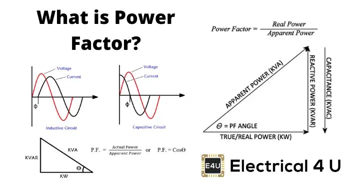
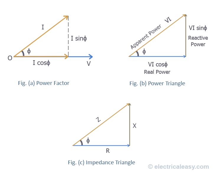
Explain in detail about Power Factor?

Power factor control panel: Components and connection diagram.

Inside the capacitor bank panel: Power factor correction, calculation
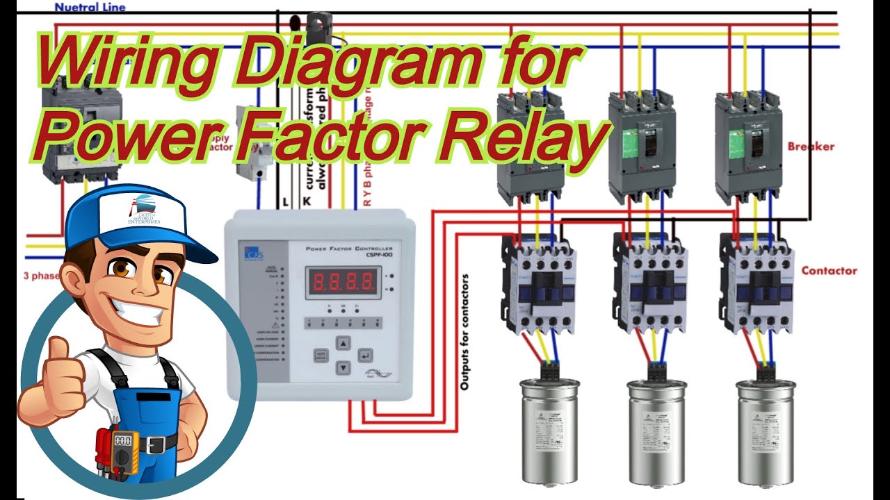
Wiring Diagram of Power factor correction relay - YouTube
What Is Zero Power Factor Method - Brent Acosta's Math Worksheets